Software Features
THE MOST OBVIOUS APPLICATION FOR A CHASSIS DYNAMOMETER IS TO GENERATE A TORQUE AND HORSEPOWER GRAPH.
THE MOST OBVIOUS APPLICATION FOR A CHASSIS DYNAMOMETER IS TO GENERATE A TORQUE AND HORSEPOWER GRAPH.
Everybody does that and we do as well. In a situation where you might be selling dyno time to a customer, the customer may just want a “number” – or a peak horsepower number so they can feel good and tell their friends. Many people look at chassis dynamometers with only this application in mind.
The Dynapack™ is capable of so much more. It is a serious diagnostic tool that serves many purposes. In this section we will show you some ways to use our product that you may not have previously thought of. Keep in mind that many of these applications are not possible on our competitors’ products.
The Dynapacks™ Software is so sensitive it can see the drop in power when the vehicles fan starts up! In this comparison screen you can see the impact of the fan on the acceleration rate, which happens when the green power line flattens, drops then continues to rise again.
This can also be seen in the second graph. The yellow and green pointers indicate where the effect starts and the loss it generated. The corresponding data to those points is displayed directly below the graph, with the loss displayed as a negative number in the blue gain box.
Note: Runs are colour coded in order of colours on the left side of the screen – red for the first run, green for the second, etc.
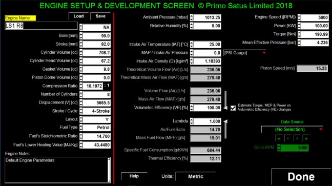
WHEN WORKING WITH NEW ENGINE PARAMETERS YOU OFTEN ENCOUNTER LIMITED EXPLANATIONS OF WHAT THE OUTCOME MIGHT BE, THEN THERE IS THE SCENARIO WHERE NO ONE REALLY KNOWS WHERE TO START WITH THE FUELLING, SO WE THOUGHT YOU MIGHT LIKE TO HAVE A PLAY WITH SOME OF THE FUNDAMENTAL PRINCIPLES THAT ARE THE FOUNDATION OF ENGINE EFFICIENCY.
We have highlighted the dependencies so that you can see how the engine parameters impact the various Mass flows, pressures, density etc.
Then we have the ability to import recorded Autoplot runs so that you can see how well the theoretical data relates to the recorded data by providing an engine rpm that will go to any chosen rpm or run through every rpm from the start to the end of the run which allows you to see relevant departures and rectify as required.
This Application is intended to be used by anyone in the automotive industry and is especially aimed at road and race car owners who want to have concise discussions with their engine builders and tuners thereby getting expected outcomes on a cost effective timeline.
Contact Dynapack to find out what format best suits your needs.
THIS IS SIMILAR TO THE TRADITIONAL DYNO ACCELERATION RUN. YOU SPECIFY A MINIMUM (STARTING) RPM AND A MAXIMUM (FINISHING) RPM FOR THE RUN.
On our dyno, you also decide how fast you want to accelerate between these points. Most other chassis dyno’s force you to accept their rate of acceleration and live with it. We can precisely control the rate of acceleration to your specification. This is extremely useful for tuning purposes.
We also hold the vehicle RPM at the starting point (called initial settling time) for a user specified period of time so the vehicle will be stabilized before starting the run. Once the dyno releases and allows the vehicle to accelerate, it will be perfectly consistent in doing so every time. Other dyno’s require you to be consistent in your application of the throttle at the beginning of the run – adding another human error factor in the mix.
We now have three different operating styles in the Autoplot mode – allowing you to choose the style that suits your needs. We have two types of step programs that step and hold the engine through the operating range – similar to the way most engine dyno’s operate. We also have a Ramp program that allows linear acceleration between two points in a specified period of time. Once the Ramp Time is chosen, the vehicle will accelerate at that rate regardless of the throttle position (above a minimum of course). Having total control over the rate of acceleration opens up a new world of tuning and diagnostic possibilities.
THIS MODE IS IDEAL FOR DRIVABILITY TESTS AND DIAGNOSIS OF LOAD RELATED PROBLEMS SUCH AS HESITATIONS AND MISFIRES. BY INPUTTING A FIXED LOAD LEVEL (THINK OF IT AS AN INFINITELY LONG HILL, WHERE YOU CAN ADJUST THE STEEPNESS OF THE GRADE) YOU CAN VARY THE RATE OF ACCELERATION AT WILL.
This load is consistently repeatable and has a very fine degree of adjustment. The load value ranges from practically no load at all, to a maximum load that will stall just about any vehicle. You can now accurately adjust “tip in” fuel or accelerator pumps or any other “transient response” type of device – and any other parameter where rate of acceleration and load is an important factor in recreating the real-world experience.
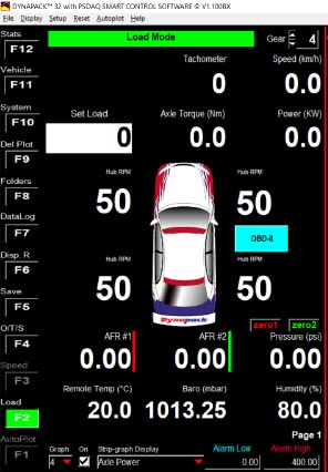
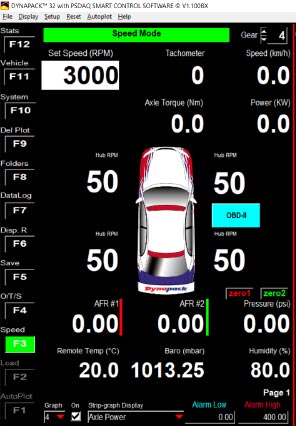
In the above screen, the white box shows the load value chosen – it can be keyed manually, or adjusted with the up and down arrow keys. The 0 value shown means there is no load currently applied and is the default setting.
This data can be exported for use in other programs such as Notepad or Excel.
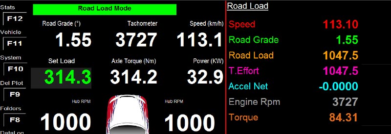
The on-road performance of the vehicle can be simulated on the dyno using Road-Load (Ctrl-F2) and Road-Acceleration (Ctrl-F3) functions.
Road Load (Ctrl-F2) provides a resistance-load equivalent to the load the vehicle would experience rolling along a smooth straight road at the current speed. As the speed increases the load increases in response, simulating the rolling resistance and aerodynamic drag on the vehicle.
Road Acceleration (Ctrl-F3) simulates driving the vehicle on a smooth straight road. In this mode the torque delivered by the vehicle, the Road Load and the vehicle’s mass all combine to produce an approximation of the vehicle’s on-road performance.
Both modes support live changes to the Road Gradient which can be ‘up hill’ or ‘down hill’ at any angle.
The selected Road Gradient and the calculated Road Load are displayed live (pictured below) and logged for in-depth analysis later.
Road Load (and Road Acceleration) modes use the 2nd order polynomial commonly used for road simulation, requiring A, B & C coefficients to perform the calculations. The A, B & C coefficients can be entered in the F11 screen on the Road Load panel, shown below.
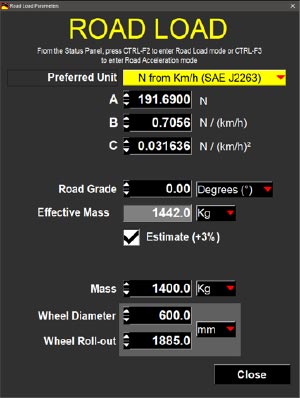
The A, B & C coefficients come from previous testing, such as a ‘Coast-down’ test.
IN THIS MODE, YOU SELECT A SPECIFIC RPM POINT WHERE YOU WANT TO HOLD THE VEHICLE. THE DYNAPACK™ WILL CONTINUOUSLY VARY THE LOAD TO HOLD THE RPM AT THAT POINT WITHIN ONE RPM AT THE AXLE.
As long as you are above the minimum throttle setting that is required to achieve that RPM, you can apply as much throttle as you want and the RPM will not rise above that point – all the way up to the full maximum rated torque capacity of the dyno. The dyno will then display the real-time torque and horsepower being absorbed, as well as other real-time relative data.
For example, let’s say you want to adjust the fuel mixture at 75% throttle and 4250 RPM. You would then input the RPM hold point and bring the throttle up until the dyno is holding the speed, and you have reached your throttle setting.
The dyno will hold this RPM point for as long as you like. You can now gradually adjust your fuel mixture at that data point and directly see the results of your actions. All of this is happening even though the vehicle is not accelerating.
Once you have found the maximum torque at this data point, you are ready to move on to the next data point. The tuning of fuel and timing maps that appear complex are now easy to work through and can be optimized without guesswork.
This cannot be said about any inertia dyno. The Dynapack™ is much easier and more precise than trying to make these adjustments while the vehicle is constantly accelerating, or by making a change and doing an entire acceleration run, then another change, then another run, as some of our competitors have to do.
Our method is faster, easier, produces more consistent results and can be precisely duplicated at any time. If serious tuning and real results are your goal, there is no other chassis dyno in the world that can compare with the Dynapack™.
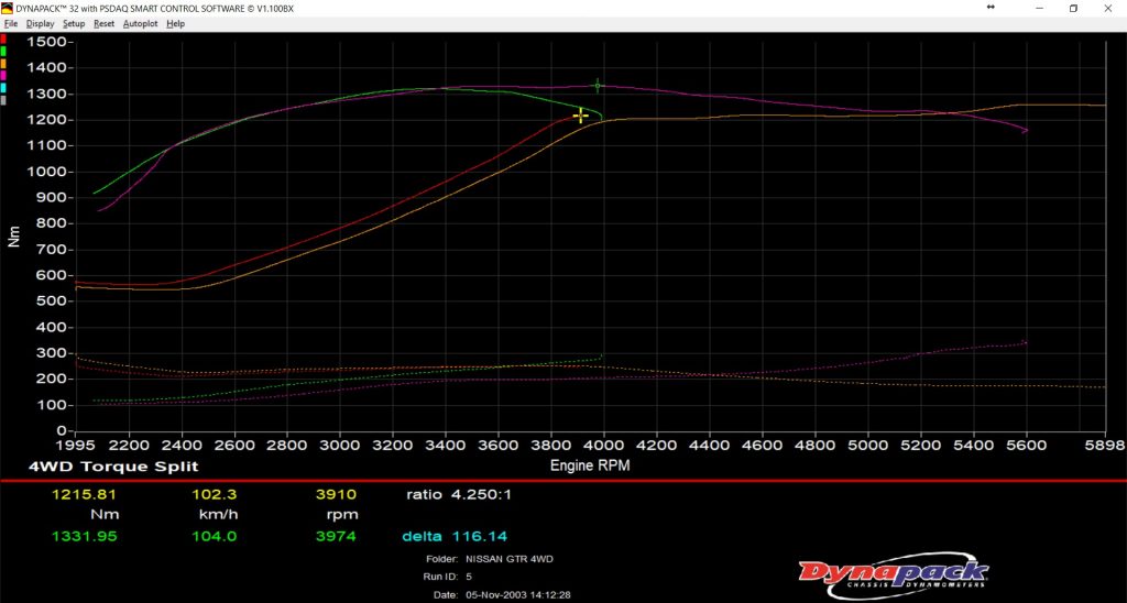
SINCE WE OFFER FOUR-WHEEL-DRIVE DYNO’S, WE ALSO SHOW YOU THE TORQUE SPLIT TO EACH INDIVIDUAL CORNER OF THE VEHICLE. WE MEASURE AND DISPLAY THOSE TORQUE SPLITS WHILE MAINTAINING EQUAL AXLE SPEED (WITHIN ONE RPM) TO EACH CORNER.
In the two-wheel mode, you can see the difference in torque applied to each side. It is important to note that our four-wheel models can be operated in the two-wheel mode by simply using only the two primary pods. If the Dynapack™ doesn’t see axle rotation on the secondary set of pods, they will be ignored and the tests will be performed in the two-wheel mode. A four-wheel-drive vehicle can even be switched in and out of four-wheel-drive as you wish.
Because the vehicle rests under its own weight on the Dynapack™, the suspension runs in its natural state. There are no straps to place additional loads or restrict suspension movement under varying torque conditions. You can actually see the suspension geometry react to the torque load and the effects of anti-squat geometry etc become readily apparent. More importantly, you can measure axle power differences in things like pinion angles, parasitic losses in different lubricants and u-joint/CV-joints, and even the pinion depth in the rear end. One of our customers was preparing a car for a race at Daytona and tested the differences between the pre-assembled third-members that they were planning on taking.
In one group, there were three housings with the same ratio and identically prepared (or so they thought). One of them measured several horsepower lower than the other two. Needless to say, they left that one at the shop. There was nothing really wrong with it; it was probably just machined a little differently by the manufacturer. Without the Dynapack™, they never would have known about it. They figured that if it had been in the car, it would have cost them several qualifying positions – or close to a tenth of a second per lap.
THE DYNAPACK™ CAN BE SET UP AS AN ENGINE TESTING RIG USING A DIFFERENTIAL IN THE FRAME AND YOU CAN THEN USE THE DYNAPACK™ AS YOUR LOAD DEVICE. THIS WAY YOU HAVE A CHASSIS DYNO OR AN ENGINE DYNO AT YOUR SERVICE.
There is a small power loss through the rear end – as there is with any drive train – but this set-up is consistent and repeatable, and will show the effects of small changes with surprising resolution, a most important factor when developing race engines or mapping ECU’s.
Since the Dynapack™ is portable, race teams can take it to the track with them. Now they can confidently compensate for weather conditions, make sure that a motor is performing as it is supposed to, diagnose problems that only occur under load, and much more. They can test a recently changed engine or transmission under load without wasting valuable track time. Knowing how inventive racers can be, we’re sure that they are going to find uses we haven’t even thought of yet.
BECAUSE THE DYNAPACK™ IS SO QUIET (INAUDIBLE WHEN THE VEHICLE IS RUNNING) NVH ENGINEERS ARE FINDING THAT THEY CAN PERFORM TESTS IN THEIR LAB THAT THEY USED TO HAVE TO DO ON THE ROAD OR ON A TEST TRACK. THE MEASUREMENTS CAN TYPICALLY BE PERFORMED MUCH MORE QUICKLY AND WITH A MUCH HIGHER DEGREE OF REPEATABILITY THAN THEY CAN GET ON A ROAD.
The Dynapack™ is also an excellent tool for tuning exhaust systems while the vehicle is running, they are hearing the things that they have never heard before. They are also able to safely do testing in the winter when road conditions are hazardous. Some engineers have commented that the reduction in liability (by eliminating hazardous outdoor winter testing and greatly reducing the amount of time their employees spend on the road) more than justifies the purchase of a Dynapack™.
Data from the supplied or compatible sensors (either standard or optional sensors) is stored with the vehicle file and is plotted graphically. All data is also available in numeric form. This data can be exported for use in other programs such as Excel.